Since the day I heard of Microsoft’s Kinect, and especially the depth sensing technology developed by Prime Sense, I was wondering how it works. To make my point clear: I do not want to steal or reverse engineer any intellectual property, try to get into their business, or help anyone doing this. I appreciate the work of Prime Sense, and I hope all their patents will make sure that they will earn what they deserve for such a great work. However, understanding how the technology actually works can help reasoning about how to make even better use of it. We could reason about upper limits in accuracy, and possible problematic configurations that should be avoided. Since people are starting to use the technology for a great variety of applications, some where accuracy is important, we should start thinking about this.
I searched through some of Prime Sense’s public patents and patent appliactions (e.g. 20100118123, 20100020078). They discribe several possibilities for the capturing process, design and realization of the speckle pattern, and image processing. It is not clear which methods are acutally in use. Clearly, it uses a structured light technique: projecting a pattern into the scene, capturing the projected pattern from an offset point of view, and computing depth from disparity (i.e. offset of the captured pattern to the “known” pattern) in the image. The fascinating part is, that kinect’s speckle pattern is constant over time, and that the depth-computations can be performed on chip (Prime Sense’s PS1080). Therefore, there must be something special about this projected pattern, that makes the computations especially simple.
On Prime Sense’s website’s FAQ they state that “The PrimeSensor™ technology is based on PrimeSense’s patent pending Light Coding™ technology”, which makes me speculate about some “code” in the pattern…
The first step in understanding the pattern is of course to get the pattern. Well, of course the pattern is in every kinect, and I strongly believe that it is the same pattern in each and every one of them, since it is a mass product. And appart from the fact that it is projected by an infra-red laser diode and therefore invisible to the human eye, it should still be fairly easy to capture it with consumer cameras; the Kinect does nothing else itself.
Searching the web, several people managed to capture the pattern in various qualities (e.g. futurepicture, nongenre, robot home, ros, anandtech or living place), tried to find some regularities in the pattern or made nice videos featuring the pattern.
They show, that the pattern is basically rectangular but severely distorted into a pin cushion. The rectangle seems to be tiled in 3×3 sub-patterns of different brightness. And in the center of these sub-patterns one point is much brighter than all the others. I will come back to these observations later.
Unfortunately, non of these approaches really mapped out the pattern. Therefore, I decided to create a map myself. Here is how I did it:
Capturing the Images
I used a fairly simple method: projecting the kinect-pattern on a wall in about 1 meter distance in a darkened room, and taking closeup photos of parts of the pattern from a distance of about 20 cm. The camera was a Fuji Finepix F30 with long exposure (1/4s, ISO 3200) in macro mode, focal length 8mm (=36mm equiv.), mounted on a low-cost tripod and using the self-timer to not shake the camera when pressing the button.
Here some snapshots of the arrangement:
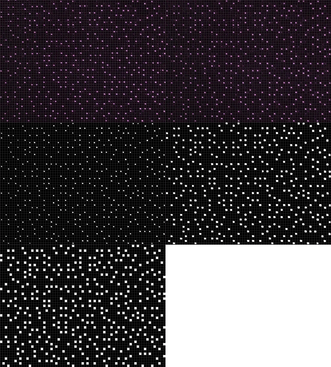
Some examples of the captured images:
In the images you see quite clearly, that the pattern is made of spots in a regular orthogonal grid. All spots are present, however only some spots are bright, the others are severely darkened. The fact of having an orthogonal grid with a more or less binary map of bright/dark spots simplifies the acquisition of the pattern. All we have to do is to create a bitmap image with one pixel per pattern-point, white is a bright spot, black a dark spot.
Bitmap from Images
In order to get this bitmap represenation from the partial pattern I did the following in Photoshop:
First I cropped the image to a rectangular region of spots, using perspective crop. Since the pattern is severely distorded (perspective distortion from the arbitrary angles between the camera, kinect and the wall; nonlinear distortions from camera optics (slight barrel distortion) and – more dramatic – the extreme pin-cushion distortion of the pattern) it is quite difficult to get a clear cropping. However it suffices as a starting point.
Then I counted the number of spots in x and y direction and resized the image so that each spot has 32×32 pixels on average. This simplifies the process of squeezing the image into a regular orthogomal form. As an helper I used Photoshops grid function, and set it to display the grid every 32×32 pixels (Preferences/Guids, Grid, Slices & Count/Grid/Girdline every 32 pixels; View/Show/Grid). In there we have to fit all the spots. To compensate for the non-linear distortions I used the free transform mode (CTRL-T) in warp mode, and dragged around misaligned spots, until all spots were approximately inside the bounds of the grid cells.
After thresholding we get a binary image, but with some remaining pixels even at the dark spots. A little erosion and dilation (in Photoshop with the Minimum and Maximum Filters) we get some nice big blobs at the bright spots, and pure black at the dark spots.
Downsampling of the image to 1/32 of its size finally gives a binary image with one pixel for every spot.
Stitching the full pattern
I did this a while along the lower edge from left to right, and stitched the resulting images into a large composite image. Stitching of the binary pixel-wise image is quite simple compared to stitching the original paintings. Just drag the new image along pixelwise, until there is no change to the overlapping pixels when turning the layer on and off.
After a while something came, I deeply hoped would come: the pattern repeated itself, after exactly 211 spots, and after exactly one third of the full pattern, something that had already been indicated in another post. After some veryfication that significant parts really repeat, I accepted this, and it saved me a lot of work. I further went upwards on the left edge, and found a repetition after 165 spots, that is again repeated 3 times.
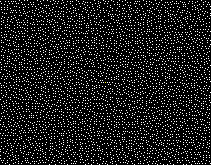
So this answers one of the questions people were asking: The pattern is composed of a 3×3 repetition of a 211 x 165 spot pattern, totalling to 633 x 495 spots, a number quite similar to VGA resolution. I am not quite sure, which camera resolution is really used in processing. According to OpenKinect the chip has SXGA resolution (1280 x 1024), timing indicates 1200 x 900 pixels, and when reading the USB stream we get 640×480. In any case, the spot pattern is either in the order of the number of pixels, or half the number of pixels, which both makes sense. The exact number is probably not that important, since the portion observed by the camera is probably smaller caused by the extreme distortion of the projected pattern, and in order to have some pattern reserved for the measured parallax effects.
I went on to complete the missing pattern, and halfway observed, that parts of the pattern bottom left seem to be present upside down on the top right part. It turned out, that the pattern is additionally 180°-rotation invariant. Although I observed it rather late, it saved me at least some image processing. I can’t imagine any algorithmical advantage of having this kind of symmetry, rather it poses an additional constraint on the pattern generation algorithm. But, I could imagine, that it has a practical issue, in that the pattern can be mounted upside down in the laser projector, without having a negative effect, making the production more fool-proof. Probably it is not even possible to distinguish the orientation of the optical element with the eye, so this invariance certainly is a good idea.
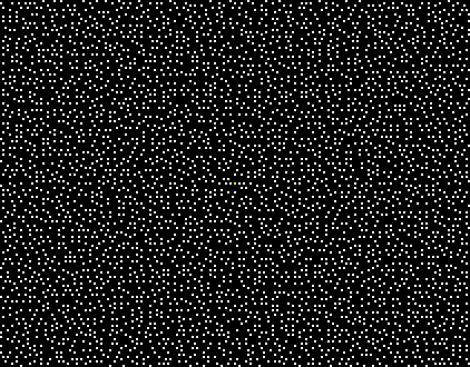
So I finally puzzled togehter the whole spot pattern. Here it is. As already mentined, the central spot is brighter. Therefore, I marked it in yellow (i know, yellow is darker than white, but you get the point).
And here the final 3×3 repetition of the pattern (Oh my god, it’s full of stars!):
Here some quick analysis results:
- The subpattern is 211 x 165.
- Both dimensions are odd numbers, so that there can be a central bright spot. The half pattern including the central lines would the be 105 x 82.
- The number of (bright or dark) spots inside the subpattern region is 34815.
- 3861 of them are bright = 0.1109 = 1 / 9.017094. Therefore, on average every 3×3 region there is one bright spot.
- There are additional spots ouside the pattern region, but they are all dark.
- No bright spots are 9-connected.
- The number of bright spots per column differ strongly between 6 and 31 (2×6, 6×8, 4×9, 6×10, 7×11, 12×12, 4×13, 12×14, 6×15, 16×16, 16×17, 10×18, 14×19, 24×20, 12×21, 14×22, 14×23, 6×24, 12×25, 4×26, 4×28, 4×29, 2×31)
- The number of bright spots per row differ strongly between 13 and 35 (2×13, 4×14, 6×15, 2×16, 6×17, 6×18, 10×19, 18×20, 10×21, 18×22, 10×23, 10×24, 12×25, 8×26, 2×27, 12×28, 2×29, 6×30, 7×31, 6×32, 4×34, 4×35)
- I found no repetitive structures from looking at it.
- The pattern is nicely tileable so that no visible seams occur due to the repetition of the pattern.
- The average brighness looks quite constant. Only above/below the center of the sub-patterns some elongated vertical darker places can be seen.
Some hypotheses on pattern design and its aid in depth processing:
- I believe there is a (rather small) region of spots, that is unique within the whole pattern and can therefore be used to uniquely determine the location in the pattern. With this possibility, getting the ID of a location and comparing it to the location of the ID in a reference image, it should be quite efficient to lookup the disparity and therefore depth for each location. This would be far more efficient than a brute-force sliding window cross correlation approach, and could be the secret behind the “Light Coding™ technology”.
- Maybe there are always 4 bright spots per 6×6 spots, that make up the pattern-dictionary? (Not checked, yet.)
- Since each bright spot is surrounded by dark spots, and the number of spots per pixel is (more or less) constant, a local thresholding operation could be implemented, that quickly filters out the spots in the sensor image, and converts it in a binary image for easy neighbor extraction and ID computation.
- Furthermore, the spot location can be computed to sub-pixel accuracy from adjacent pixel values, therefore increasing depth precision.
- Slanted projections should no be a strong problem as long as individual spots can be identified in the neighborhood.
- Depth discontinuities, missing spots, or strongly varying albedo on the projected object will pose problems, that have to be solved. Maybe with some of the region growing approaches mentioned in the patents. Maybe even simpler with a filtering step (Is this the 0x0016 Command for Depth Smoothing in the USB-Protocol)?
- If the actual algorithm is based on these assumptions, I believe that the depth values will only be correct at bright spot locations, and that all the other pixels of the returned depth image are somewhat filled in. I think, that should be considered, when using the sensor for e.g. measuring purposes…
Final thoughts on the 3×3 repetitive pattern design and the central bright spots:
The 3×3 repetition of the sub-pattern does not have any algorithmic advantages, rather the disadvantage that disparity has to be limited to one third of the pattern, because we then would not be able to differenciate between the 3 potential disparities. I believe that it is a necessity (or at least simplification) in production of the laser projector. According to Patent Application “OPTICAL DESIGNS FOR ZERO ORDER REDUCTION” (especially Fig 3A) there are two difraction gratings. One that makes a regular grid from the laser beam that could be modulated on a per-spot basis to form one sub-pattern. And a second one, that multiplicates the pattern exactly in a tileable fashion into the 3×3 full pattern. And, if I interpret it correctly, the bright central spots are a side-effect of the diffraction grating. This effect is also visible at diffraction pattern images e.g. at CNIOptics.
Patent Application OPTICAL PATTERN PROJECTION even shows a picture of the exact 3×3 repetition, and the strong pin-cussion effect, which seems to be another side effect.
Further, I believe that the brightness vatiations between the sub-patterns are another side effect, and not an algorithmical necessity as others mentioned. Finally, the dark spots outside the pattern region could be simply another repetition of the patterns, that is maybe additionally attenuated.
I found another indication that there could be a diffraction pattern to multiplicate the sub-patterns: Look at the laser-projector output window (best if turned off, do not hurt your eyes). It shimmers in all colors, typical for diffration gratings. Now point it to a light source so that you can see the reflection of the lightsource. If you slowly tilt it, another reflection can be seen. If you look around, there are reflections at angles approximately in a rectangular grid around the original reflection. If I am not wrong, the angles between the reflections are very similar to the angles between the sub-patterns.
I hope this report is helpful for all who have the same questions as I have. If you have other findings, or comments or if you find some mistakes here, please let me know.


